Recipient block holders are held very firmly in place by two magnets located on the base plate. To remove (or change) the recipient block holder, slide the block holder towards the front of the arrayer baseplate until you are able to lift it up by using the thumbs.
If the digital readout does not respond to the control buttons or knob, or if the readout is dim, the micrometer battery may be too old and needs to be replaced. Batteries are located on the underside of the micrometers, and are accessible through the circular holes in the base plate. Reposition the arrayer carefully to gain access to the battery covers. Insert a new battery with the positive (+) side away from the cover, tighten the cover, and check to verify that the micrometer numbers change as you twist the handle. You may need to reinsert the battery two or three times before the battery correctly activates the readout. We recommend Renata type 2450 batteries because some other makes may not fit. A small booklet specifically about the micrometers is included with the arrayer and will provide more information about the micrometers.
Tighten the turret pivot screw in 1/8-inch increments until the swinging turret motion is just blocked – do not overtighten.
Make sure that both its locknuts are completely loose: the black knurled ring near the base of the handle and the silver knurled knob at the side of the slide.
If the array block is made in very high density, there may be an accumulation of residual paraffin, partly caused by the slight size difference between the sample tissue cores and the holes in the array. This makes the middle part of the tissue array protrude upwards, and this phenomenon becomes visible after arraying a large number of samples. In essence, you may be trying to fit too many samples in too little a space. To prevent this, either increase the spacing between adjacent array samples or make the holes in the array block deeper. To flatten any existing outgrowths in the tissue array, warm the block to 35-37 ° C for 15 minutes. While the block is still warm and elastic, place a clean microscope slide on top of the array block, and carefully press downward until all the specimens are at an even level. Let the block cool before removing the slide.
Yes. Just remove that sample with the small punch and place a new sample in the same position.
The sharpened edge of the punch tip is probably distorted. Change the punch.
This situation can be corrected by gently pushing the stylet down against the sample before trying to extract it (tamping). Placing pressure on the top of the sample causes it to compress axially and expand radially, thus creating a tighter fit within the punch tube. Rotating the needle handle slightly also helps break the sample from its base. Longer core samples are also easier to extract than shorter core samples. This is particularly important with the larger punches (1.0, 1.5, and 2.0 mm diameter).
Make sure the punch handles are always turned to a consistent position.
The punch may be bent. Check it and change if necessary.
Make sure that you are not accidentally moving the turret while pushing down the sample.
Punch alignment may have changed (for example, after replacing the punch). Realign the punch.
First, to verify punch alignment, place a blank paraffin block in the recipient block holder. Press the smaller punch down until it leaves a mark in the paraffin surface. Move the turret to switch the larger sampling punch in position, and again make a mark on the paraffin surface. Adjustment is needed if the marks are not coincidental. Punch holes that appear one in front of the other need front to back adjustment; holes to the side of each other require left-to-right alignment.
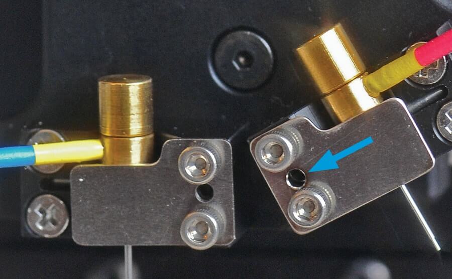
Fig. 1. Adjusting front-back alignment of a punch.
Front to back alignment is adjusted by setscrews recessed in the inboard side of the plastic v-blocks holding the punches. These screws are accessed through the small hole in the stainless steel clip that holds each punch (see Fig. 1). To adjust the punches loosen all four screws holding that v-block before using the smallest hex key to advance the setscrew a small amount by turning it clockwise. Re-tighten all four screws and recheck the degree to which the two punches create a hole in the same location. Repeat if necessary.
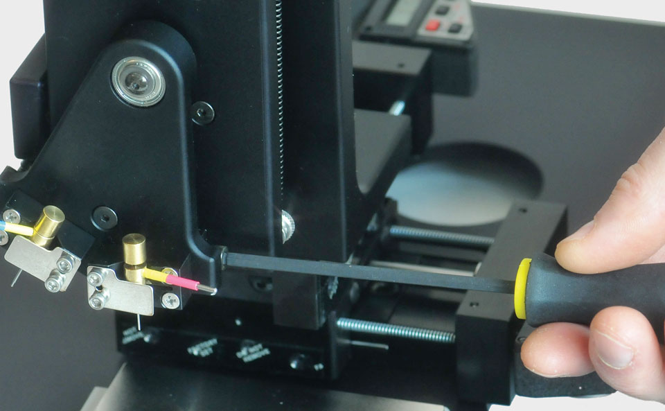
Fig. 2. Adjusting right-left alignment of a punch.
To correct left-right alignment, use the largest hex key to turn the left-right setscrews on each lower side of the turret (see Fig. 2).
For the most accurate realignment of punches, align punches (front-back or left-right) with their punch handles in a consistent position, such as having both handles extended out to their respective sides. Then, when punching, make sure both handles are in those same positions to eliminate any position errors caused by an eccentricity or bend in the punches.